Info Topic zu Aux Moddingboards
die meisten boards Boards in 5 Varianten verfügbar, wobei aber v1.5 überholt ist
Generation 1.0 High/low fähig, aber damit verbundene Helligkeitsänderung je nach Zellspannung
Generation 1.2 LEDs sind mit Konstantspannung betrieben, ohne LVP
Generation 1.5 unstabilisierte Spannung + LVP
Generation 1.7 konstante Helligkeit LDO + LVP
Generation 2.0 High/low + LVP
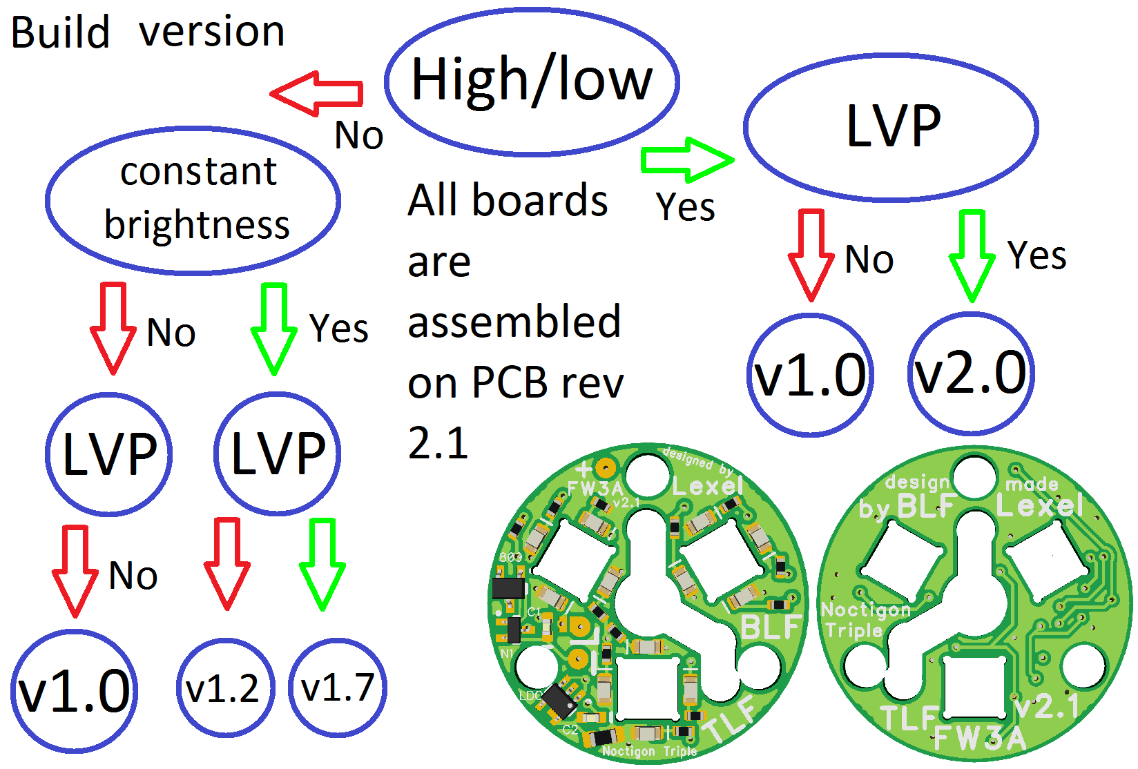
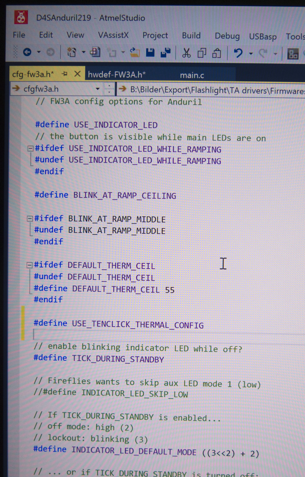
- Version mit LDO → ON/OFF kein MCU Dimming
→ flash mit #define INDICATOR_LED_SKIP_LOW Einstellung
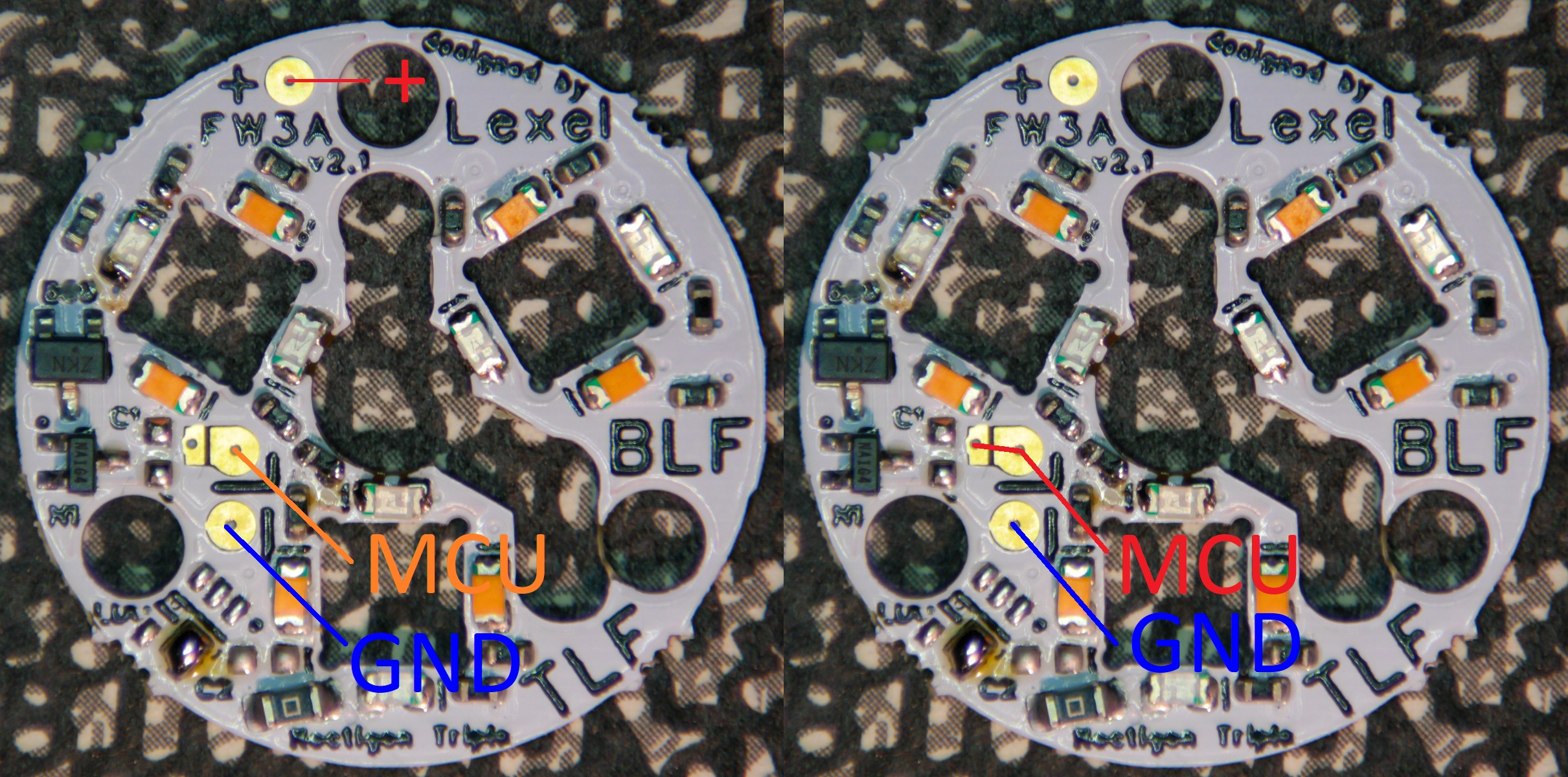
- Version mit LVP → Schutz vor Tiefentladuing bei langer Lagerung
LDO → constant brightness and color mix over full battery voltage
LVP → shuts down when battery low (2.93V without MCU, 3.3V with MCU used)
.
LVP chip schaltet bei 2.93V ab
Wenn die MCU für Aux Kontrolle benutzt wird in 2 Leiter Betrieb muss man ca. 0.35V draufschlagen
- also über 3.3V alle LEDs an, darunter aus
3 Leiter Betrieb (zwingend nötig nur bei v2.0)
- also über 2.93V alle LEDs an, darunter aus
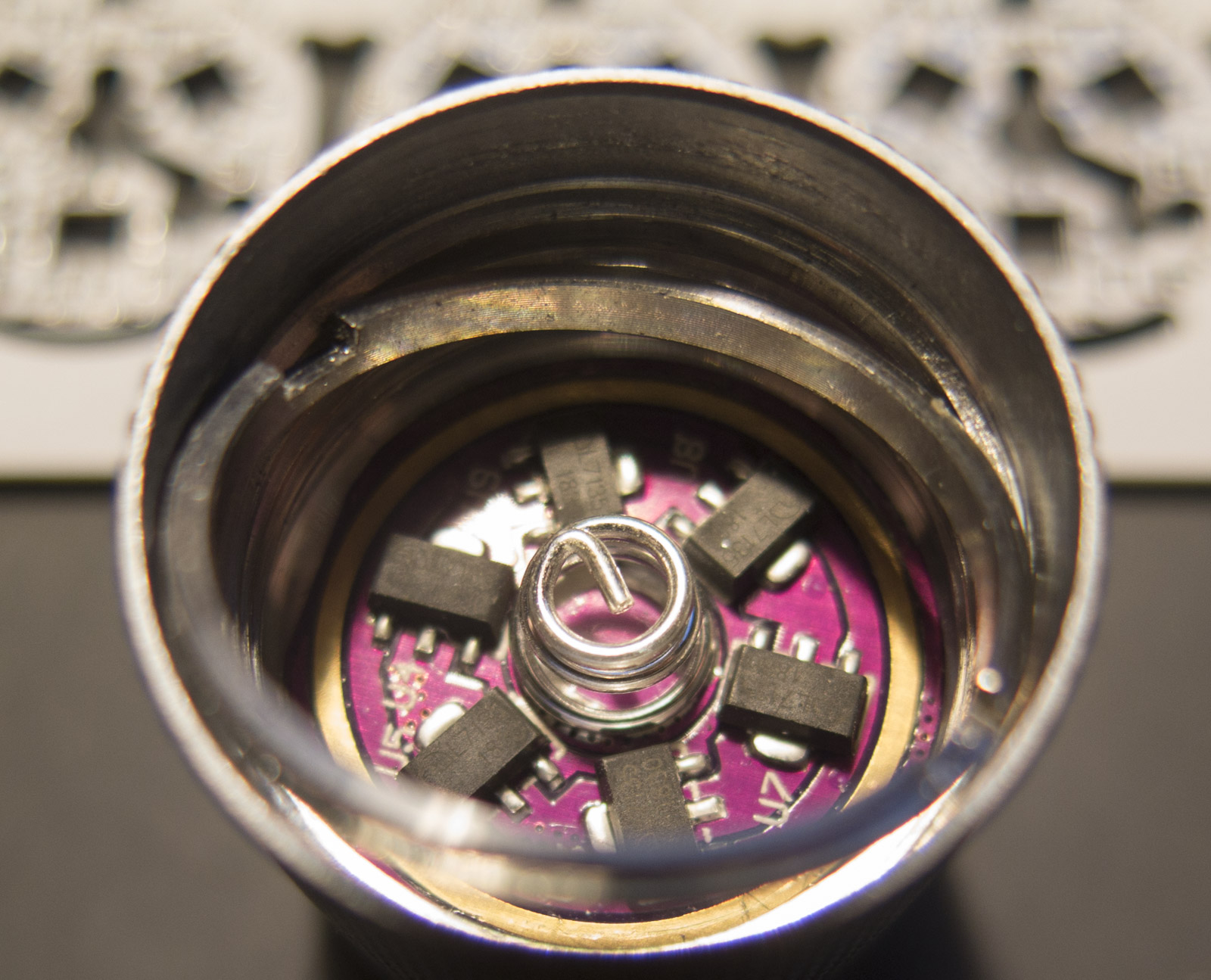
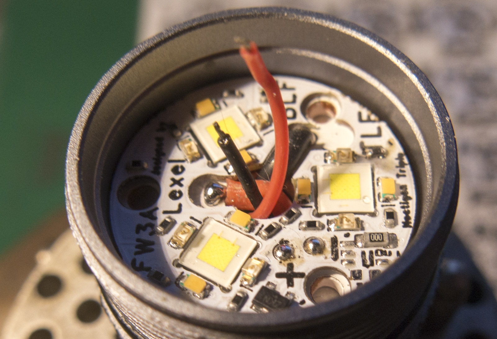
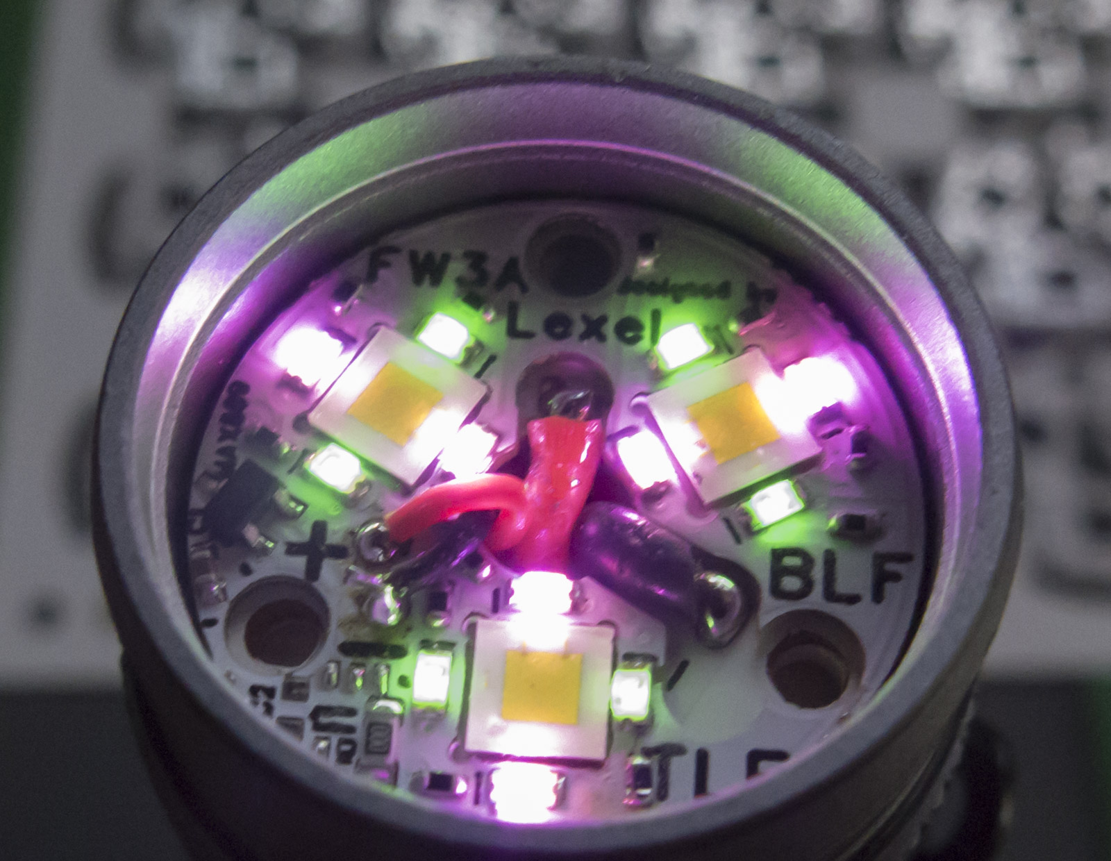
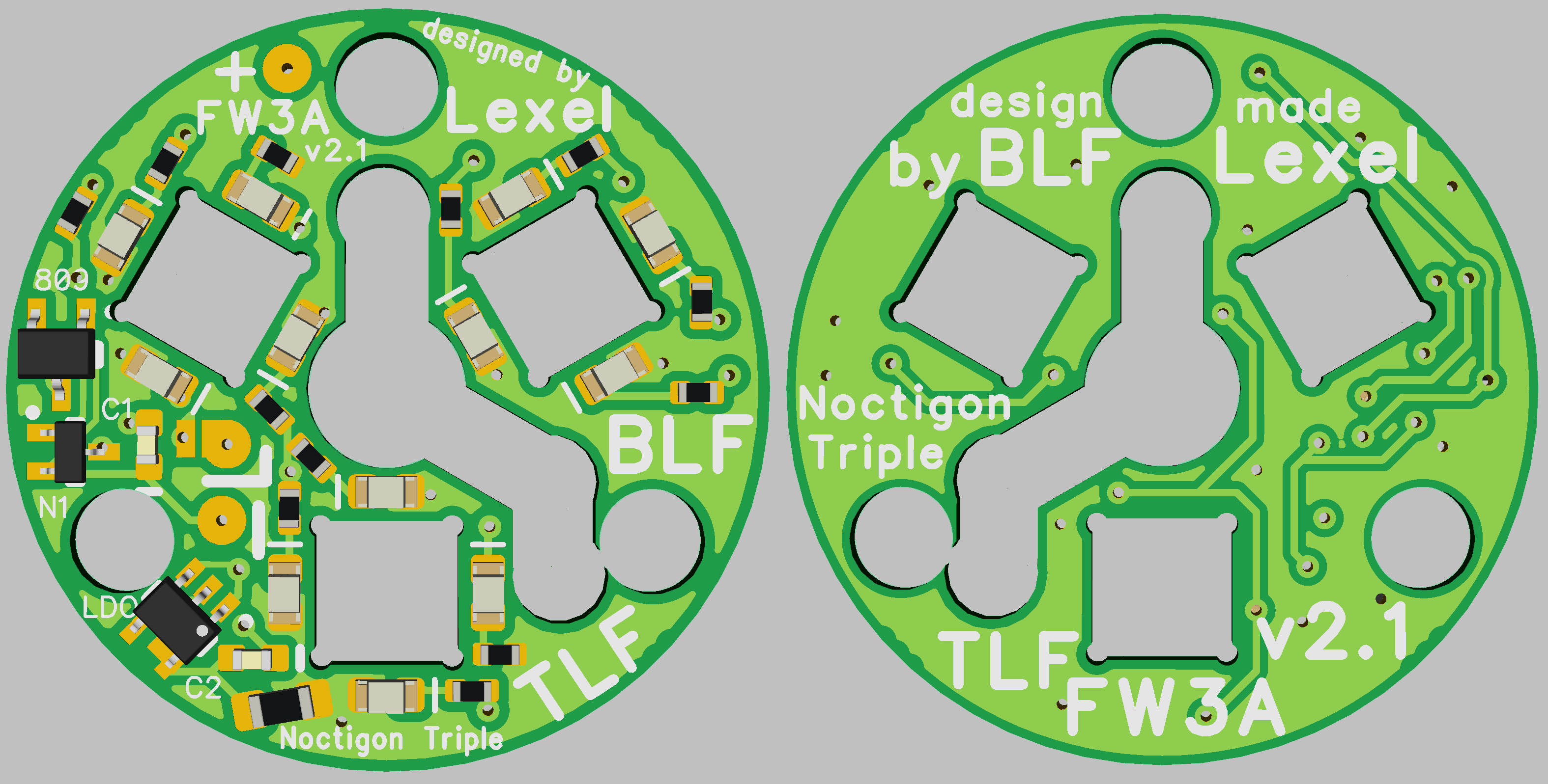
Passt bei FW3A und Noctigon Triple
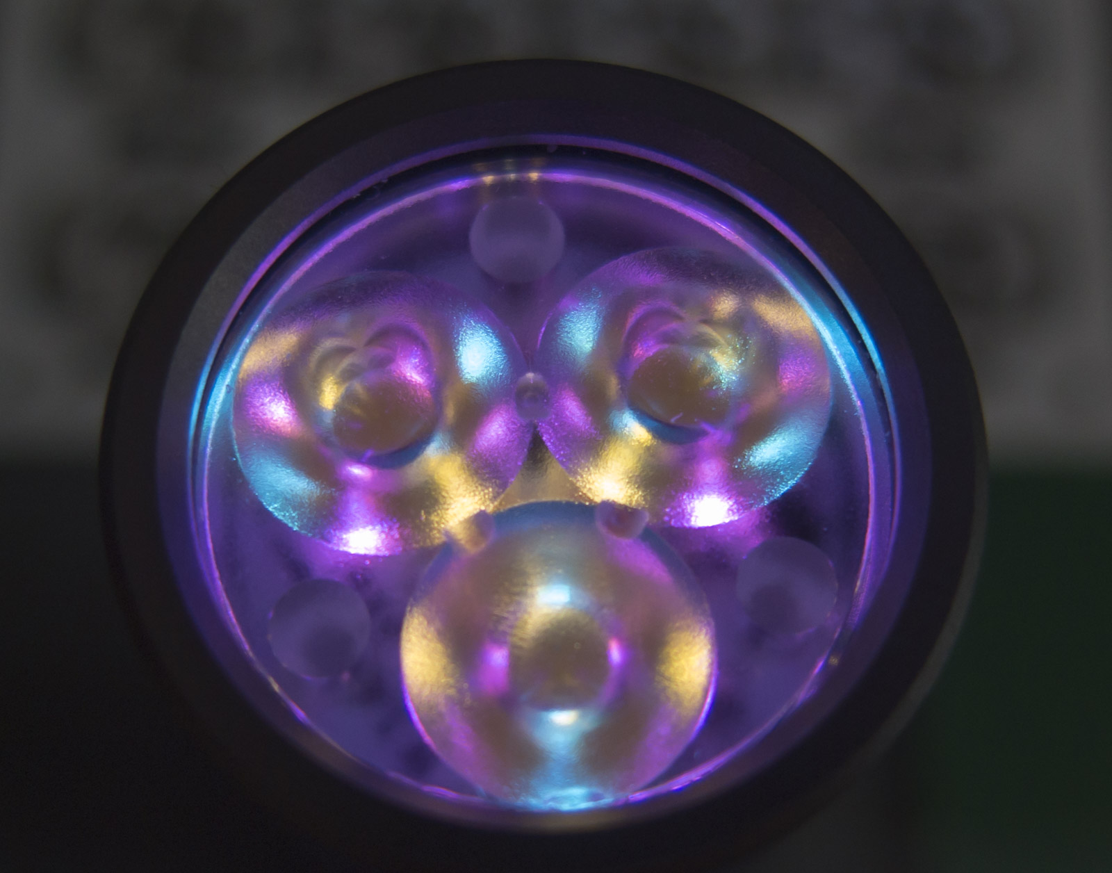
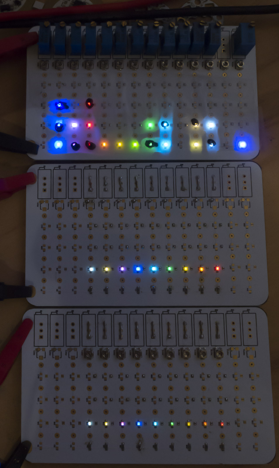
Beispiel mit warm white, ice blau und pink
.
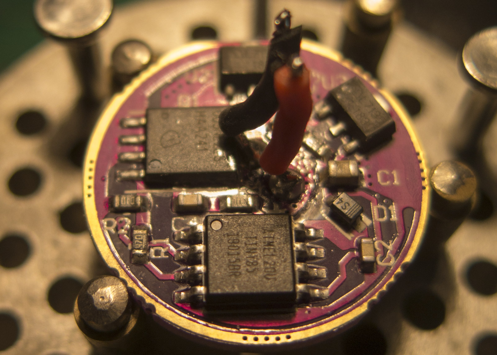
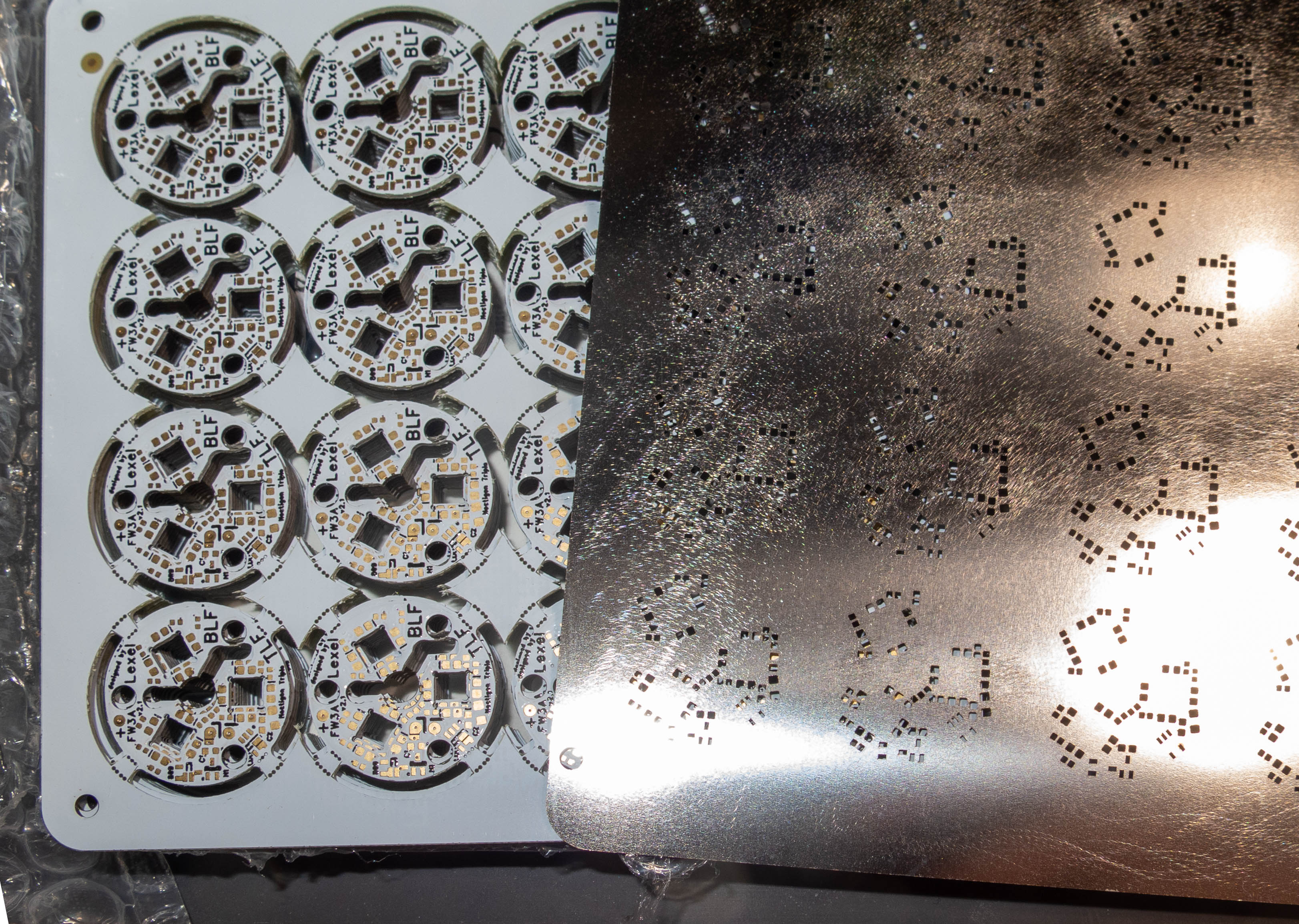
Produktionsboard v2.1 und stencil sind da
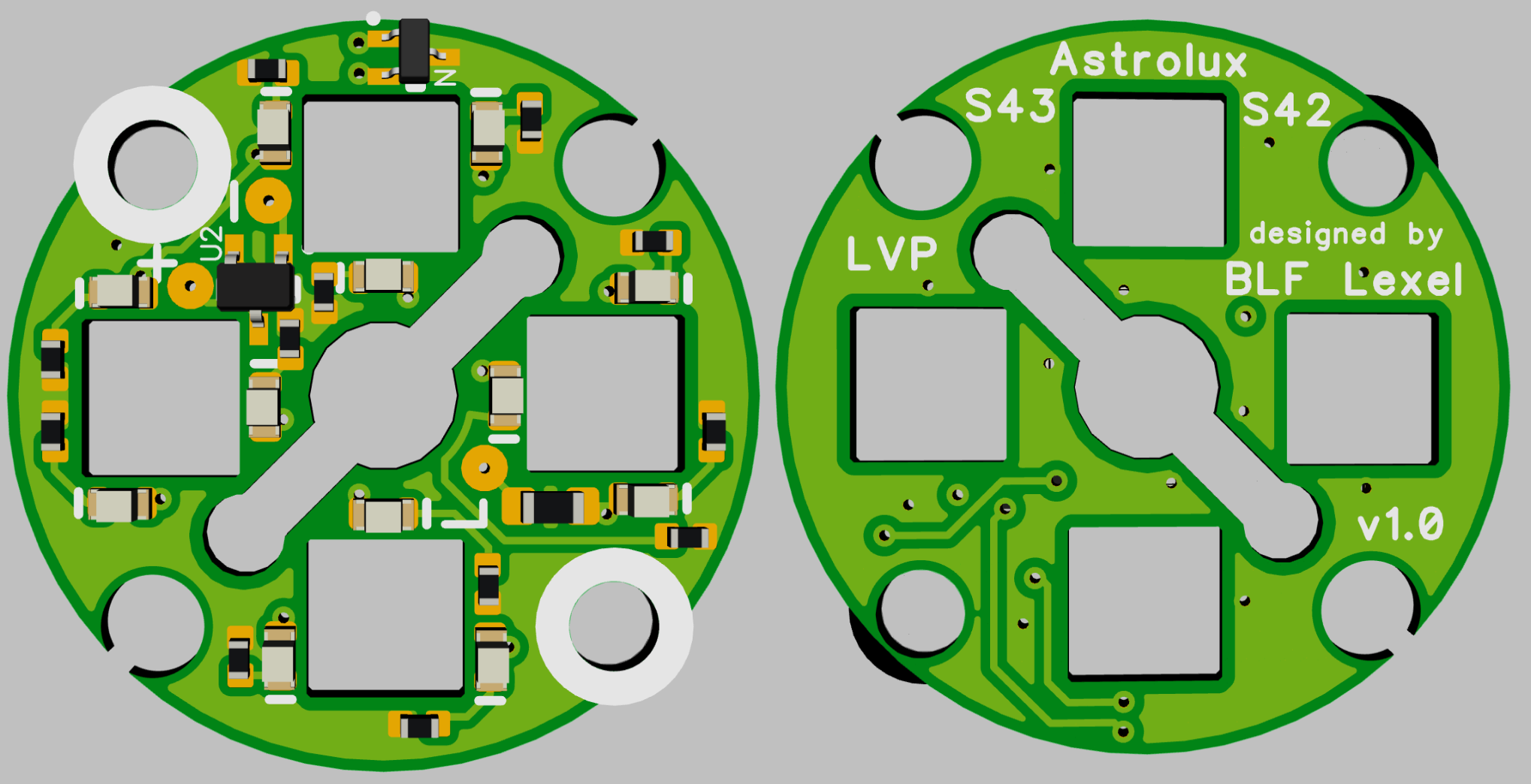
Astrolux S42 und 43
v1.0 und v2.0 möglich
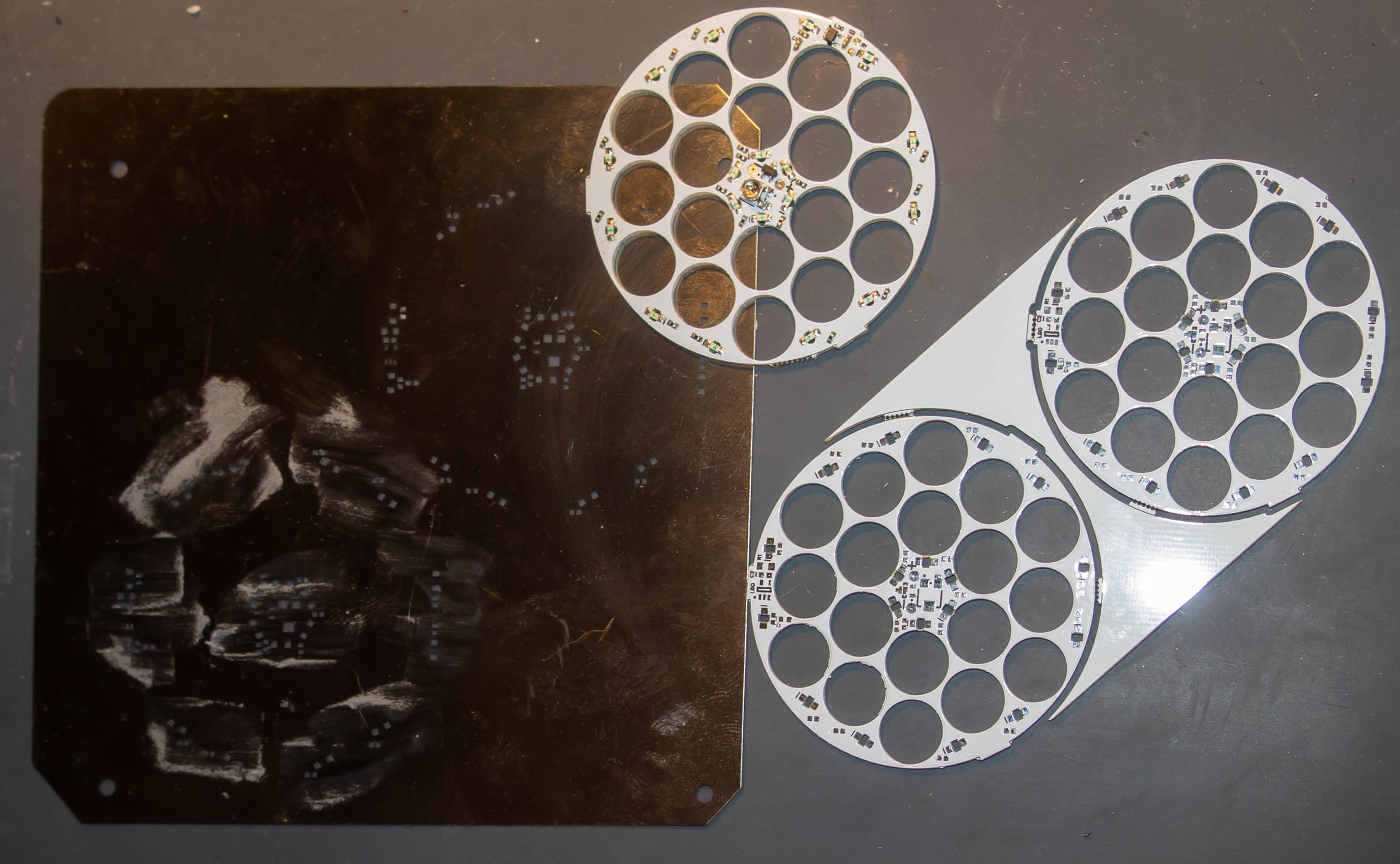
Emisar D18
v1.0 bis v1.7 möglich
zusätzlich ein Trimmer
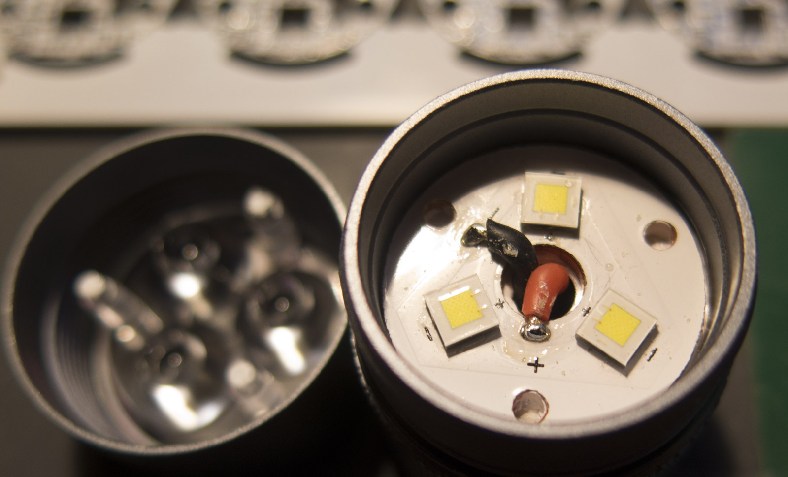
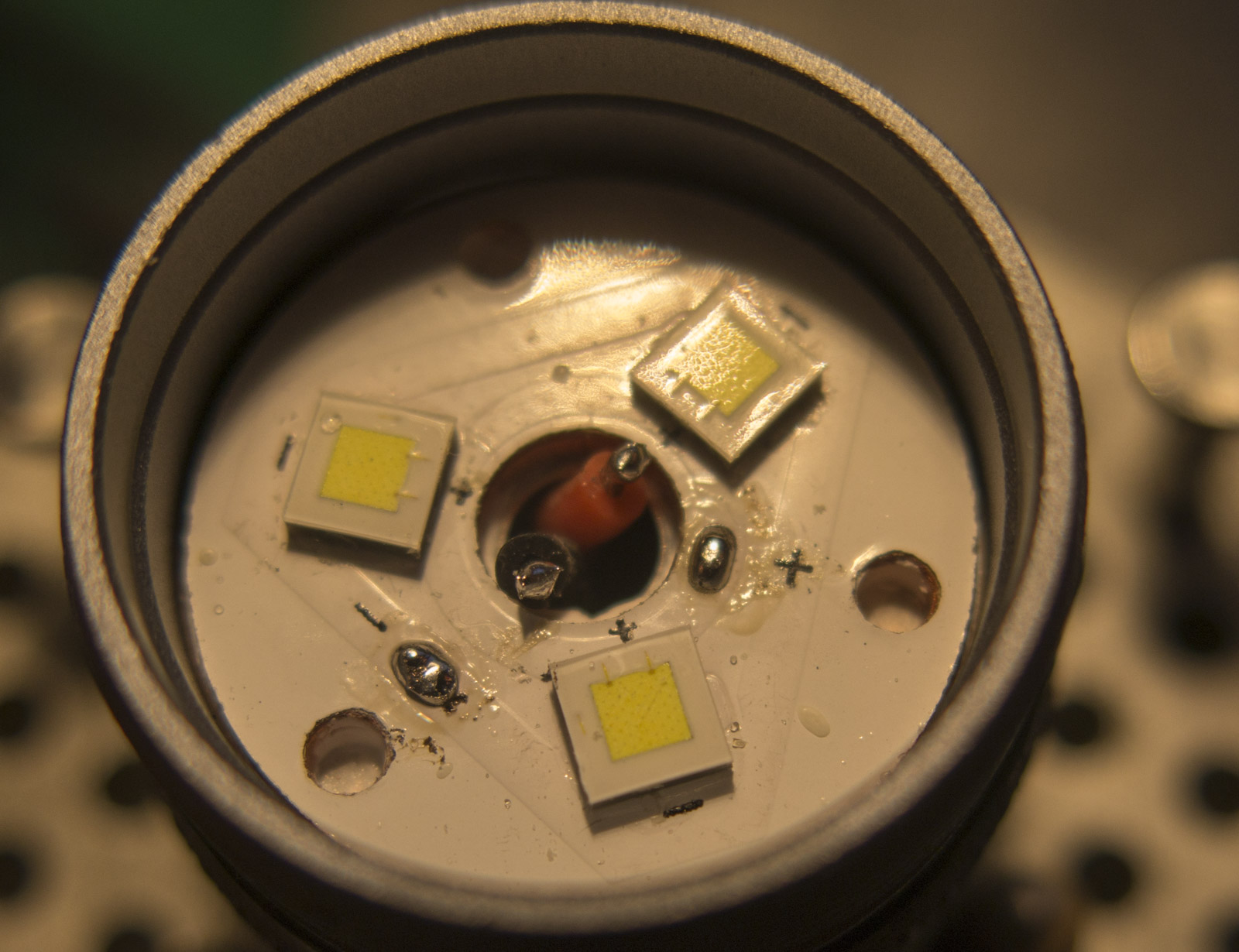
Jede Farbkombination möglich, da jede LED einen eigenen Balance Widerstand hat
.
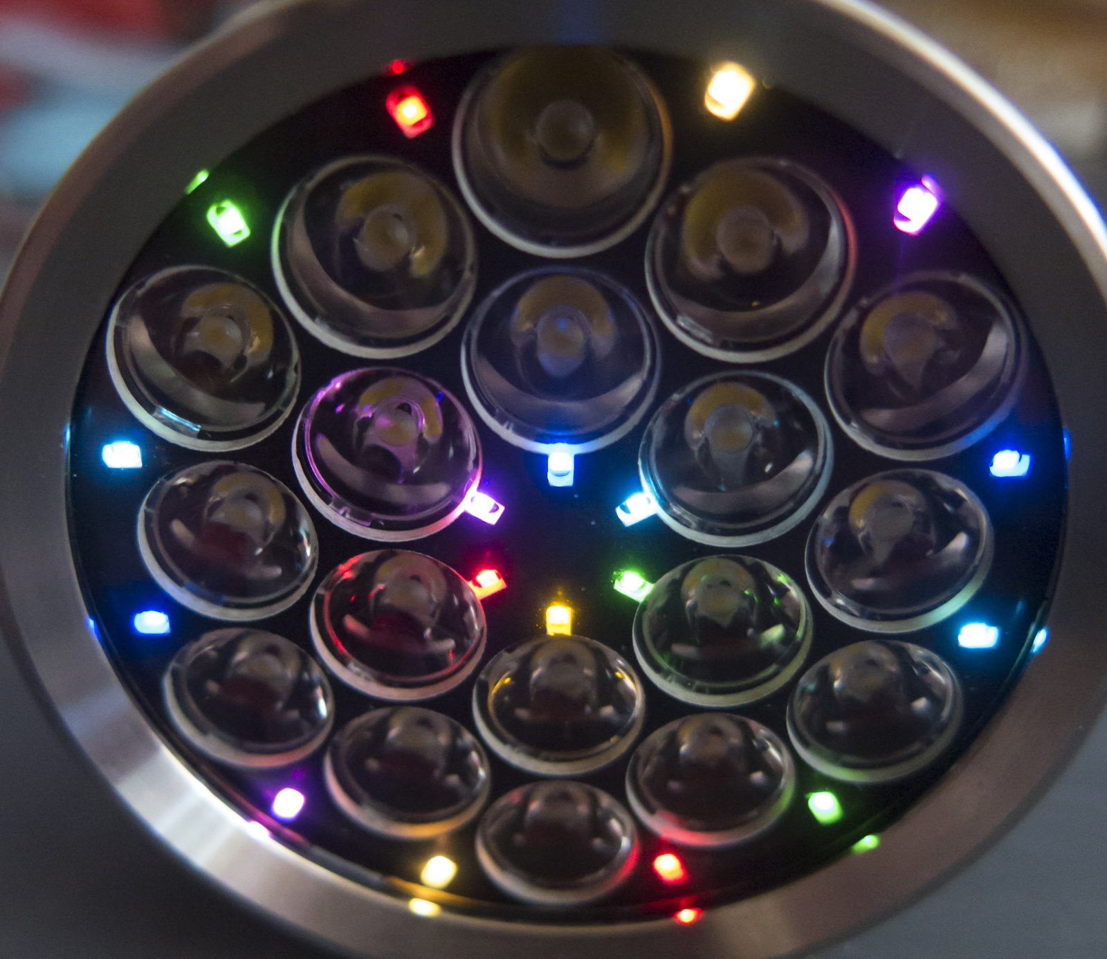
LEDs wie gewünscht, jegliche Muster und Kombination möglich
Blau, pink, rot, orange, gelb, grün, eisblau, WW, CW (Gelbgrün ist zu ineffizient)
Neues LED batch Vergleichsboard für 3 Abgleich von 3 Helligkeitsleveln
[LED Farben] (je weiter oben, desto effizienter)
LED Farbstromaufnahme pro LED basierend auf meiner “medium 0.5mA” Skala
green 19.1uA
blue 21.2uA
ice blue 25.2uA
pink 30.7uA
CW 38.7uA
WW 40.2uA
red 50.9uA
orange 124uA
yellow 206uA
5 Helligkeistlevel “1mA”, “0.75mA”, “0.5mA”, “0.3mA” and “0.15mA”
die genaue Stromaufnahme der LEDs lässt sich errechnen
Es ist aber auch möglich das Board auf z.B. 0,5mA zu bauen und die Helligkeit richtet sich nach dem Strom
die meisten boards Boards in 5 Varianten verfügbar, wobei aber v1.5 überholt ist
Generation 1.0 High/low fähig, aber damit verbundene Helligkeitsänderung je nach Zellspannung
Generation 1.2 LEDs sind mit Konstantspannung betrieben, ohne LVP
Generation 1.5 unstabilisierte Spannung + LVP
Generation 1.7 konstante Helligkeit LDO + LVP
Generation 2.0 High/low + LVP
- Version mit LDO → ON/OFF kein MCU Dimming
→ flash mit #define INDICATOR_LED_SKIP_LOW Einstellung
- Version mit LVP → Schutz vor Tiefentladuing bei langer Lagerung
LDO → constant brightness and color mix over full battery voltage
LVP → shuts down when battery low (2.93V without MCU, 3.3V with MCU used)
.
LVP chip schaltet bei 2.93V ab
Wenn die MCU für Aux Kontrolle benutzt wird in 2 Leiter Betrieb muss man ca. 0.35V draufschlagen
- also über 3.3V alle LEDs an, darunter aus
3 Leiter Betrieb (zwingend nötig nur bei v2.0)
- also über 2.93V alle LEDs an, darunter aus
Passt bei FW3A und Noctigon Triple
Beispiel mit warm white, ice blau und pink
.
Produktionsboard v2.1 und stencil sind da
Astrolux S42 und 43
v1.0 und v2.0 möglich
Emisar D18
v1.0 bis v1.7 möglich
zusätzlich ein Trimmer
Jede Farbkombination möglich, da jede LED einen eigenen Balance Widerstand hat
.
LEDs wie gewünscht, jegliche Muster und Kombination möglich
Blau, pink, rot, orange, gelb, grün, eisblau, WW, CW (Gelbgrün ist zu ineffizient)
Neues LED batch Vergleichsboard für 3 Abgleich von 3 Helligkeitsleveln
[LED Farben] (je weiter oben, desto effizienter)
LED Farbstromaufnahme pro LED basierend auf meiner “medium 0.5mA” Skala
green 19.1uA
blue 21.2uA
ice blue 25.2uA
pink 30.7uA
CW 38.7uA
WW 40.2uA
red 50.9uA
orange 124uA
yellow 206uA
5 Helligkeistlevel “1mA”, “0.75mA”, “0.5mA”, “0.3mA” and “0.15mA”
die genaue Stromaufnahme der LEDs lässt sich errechnen
Es ist aber auch möglich das Board auf z.B. 0,5mA zu bauen und die Helligkeit richtet sich nach dem Strom